Citat:
44250:
Kad dodjem kuci pisacu tacno o kojem dijelu "dc-nosa" mislim,i postaviti sliku postojeceg stanja esp33 i mojeg misljenja kako bi to mozda moglo.
Evo ovo sam mislio:
The Detector
This is the most important of the functions. It must be capable of detecting a DC offset of
either polarity, and be immune to the effects of asymmetrical waveforms and low frequencies.
This is a common requirement, and it is most expedient to use a simple (single pole) filter to
keep the complexity to a minimum. With this arrangement, a low frequency cut-off of about
1Hz is about right. Without boring you with the mathematics behind this, it works out
(eventually) that a filter having a time constant of 1.0s will still provide the ability to detect high
level DC reasonably quickly, but allow low frequencies through without triggering. With this,
the relay could have its supply removed within about 50ms from the time the output voltage
reaches the supply rail (this is supply voltage dependent) - due typically to a shorted transistor
in the output stage. By changing the time constant of the filter, we can adapt the circuit for
operation at other higher frequencies to suit a biamped (or triamped) system.
The detector can be built using an opamp, and will work very well, but this introduces the need
for low voltage supplies within the power amp. This is not always possible (or desirable), so
the design uses discrete transistors throughout to allow for the different supply voltages found
in typical power amplifiers.
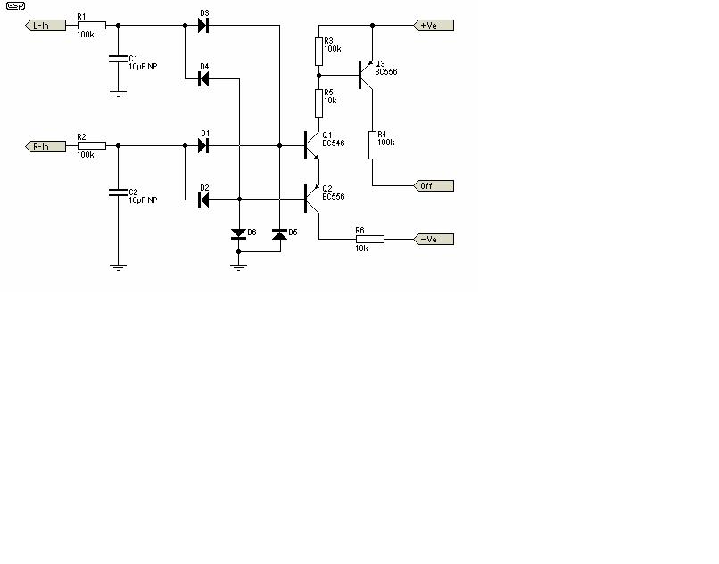
The detector circuit shown in Figure 1 (1) is simple and works well, and as shown will not
trigger with a 30V RMS signal at 5Hz, but operates in 60ms with 30V DC applied, and in 50mS
with a 45V DC supply. This should be sufficient for most applications, and allows the use of a
non-polarised electrolytic capacitor in the filter. These are cheap, small and quite adequate for
this purpose.
NOTE: The power supplies (+ve and -ve) shown in these diagrams will normally be the power
amp supply rails. Do not try to substitute different supplies unless you know exactly what you
are doing, or the circuit may not work properly. This is especially true of the muting circuit, but
incorrect supplies will (may) also affect the DC detection circuit. Like most of my projects, this
is intended for experienced constructors."
http://sound.westhost.com/project33.htm (3 of 12) [24.3.2009 16:28:59]
A ovako sam ja mislio da se preradi ulaz tako da vidi praktično četiri ulaza:
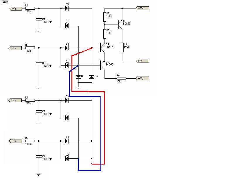
Dakle sve isto samo još dodata dva "čistača" AC od DC na postojeća dva. Da li bi to moglo da radi,i da li bi se umjesto jednog bipolarnog od 10uF mogla koristiti dva elektrolitska od 22uF vezana antiredno,da li bi to šta mijenjalo?
Evo dole ispod komplet pdf fajla sa ESP stranice:
[Ovu poruku je menjao 44250 dana 02.10.2012. u 21:28 GMT+1]
"nikad se ne raspravljaj sa budalom -
spustiće te na svoj nivo i pobediti
iskustvom"


 Re: Hi-End Pojacavac 70+W(LM3886-most) by:Dragoljub Aleksijević, Macola


